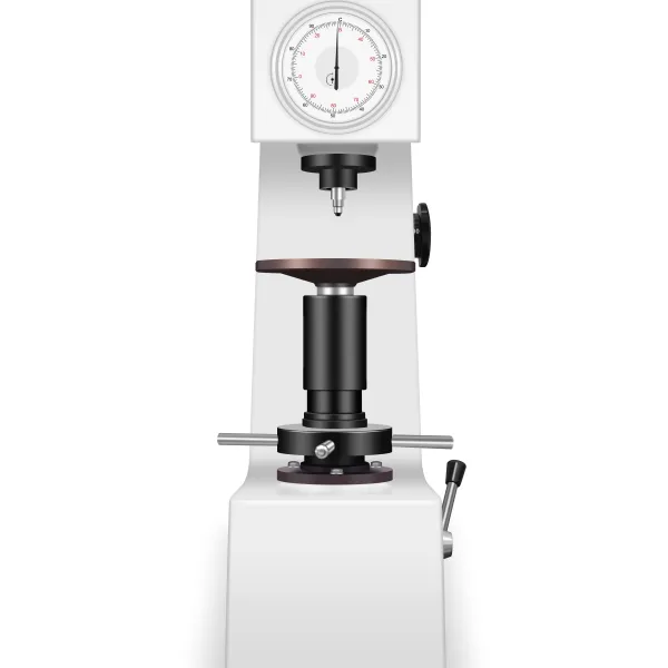
A workpiece fitting inside a hardness tester does not necessarily mean that the indenter can reach the required test point. Before selecting equipment, check the complete test position: available measurement space, access for the indenter and measuring system, and support for the part under load.
Mark each specified test point on a drawing or on the workpiece itself. Record its position relative to the part’s outer surfaces, edges, shoulders and bores. For large or irregular components, include the orientation in which the surface must be tested and the space needed to load and position the part.
Also identify the material, expected hardness range, surface condition and applicable test method or standard. These factors affect both the equipment choice and whether the test location is suitable for a valid measurement.
Use the candidate equipment’s dimensional drawings and technical documentation for these checks. A nominal opening or reach dimension alone may not describe every obstruction at the intended position.
The indenter must contact the intended surface in the orientation required by the selected method. Check the space around the indenter and its holder, not just the tip. For methods that require optical indentation measurement, confirm that the measuring system can also view the impression at that location.
A point may be physically accessible but too close to an edge for the selected procedure. Edge effects and inadequate support can influence the result. Check the applicable standard and test procedure for minimum distances from edges and between indentations; do not assume one spacing rule applies to every method or material.
Check the bore diameter, depth and entry path against the complete testing assembly. A recessed or curved surface may prevent correct contact, stable positioning or optical measurement. Confirm whether the chosen method and applicable standard permit testing that surface, and whether suitable equipment or fixtures are available for the geometry.
During a hardness test, the part must remain stable without rocking, slipping or deflecting appreciably. A support or fixture should suit the workpiece geometry and allow the test force to be applied as required by the method. Check that the support does not obstruct the test point or interfere with the indenter.
For a large component, consider the weight and balance of the entire part, not only the area under the test point. If a portable tester is being considered, check the access and stability requirements for that specific device and method; portability alone does not establish suitability.
JCTEST can review the intended application using the material and expected hardness range, a dimensioned part drawing, marked test locations, the required standard and any constraints on moving the workpiece. Include photographs of obstructed areas and details of the expected test frequency or data-output needs where relevant.
Specific clearance, capacity, test-force and functionality requirements should be confirmed against the formal technical documentation for the equipment under consideration. Contact JCTEST via WhatsApp to discuss the proposed setup.