High-Precision Metallographic Cutting Machine: Preventing Heat Damage and Deformation in Sample Preparation
16 04,2026
Jin Cheng
Technical knowledge
Accurate microstructural interpretation starts with a cut surface that is clean, flat, and thermally unaffected. This article explains the critical role of a high-precision metallographic cutting machine in laboratory sample preparation, focusing on how stable spindle speed, precise feed control, and an optimized cooling system work together to minimize heat buildup, oxidation, and mechanical distortion. Typical application scenarios—including failure analysis for crack identification, grain size measurement, and phase evaluation—are used to demonstrate why low-damage cutting is essential for reliable microscopy results and repeatable data. By comparing professional high-precision cutting solutions with traditional cutting methods, the article highlights common risks such as smearing, edge rounding, and contamination, and provides practical criteria for judging cut quality along with parameter-setting guidance for different materials. Designed for materials science and metallography labs seeking standardized workflows, the key message is clear: high-precision cutting enables reliable analysis and improves confidence in downstream metallographic results.
High-Precision Metallographic Cutting: How to Prevent Heat Damage and Deformation Before the Microscope Tells the Truth
In metallography and materials testing, the most expensive instrument is not always the microscope—often, it is the assumption that the sample surface still represents the real microstructure after cutting. When heat-affected zones (HAZ), smearing, burrs, or microcracks appear during sectioning, they can quietly distort grain boundaries, phase contrast, crack tips, and inclusion morphology—making “accurate analysis” look convincing but wrong.
Core value in one line:High-precision cutting = reliable analysis. In failure analysis, grain size measurement, and phase identification, the cut is not a preparation step—it is a data integrity step.
Why Heat and Deformation Happen (Even When the Cut “Looks Fine”)
Heat damage and mechanical deformation typically come from a combination of unstable spindle speed, excessive feed force, insufficient cooling flow, and mismatch between wheel specification and material. Even a narrow HAZ—often 10–100 μm in many steels under aggressive cutting—can change etching response and blur the boundary between “true structure” and “cut artifact”.
Common symptoms labs misinterpret as “material issues”
Recast/tempered layer or discoloration near the surface after etching
Smearing on ductile alloys, masking inclusions and second phases
Edge rounding and burrs that hide crack origins or notch geometry
Microcracks initiated by vibration or overload, later “confirmed” as service damage
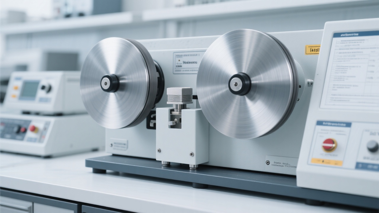
What Makes a High-Precision Metallographic Cutter Different
A high-precision metallographic cutting machine is built around repeatability: stable rotational speed, accurate feed, and a cooling system designed to remove heat before the microstructure pays the price. For labs seeking standardization, it also reduces operator variability—one of the most overlooked contributors to inconsistent results across shifts or sites.
1) Stable RPM: less heat accumulation, less vibration-driven damage
In real cutting, load fluctuations can cause RPM droop. When speed drops unexpectedly, the wheel may rub instead of cut—creating friction, heat, and smearing. High-precision systems maintain speed under load, helping keep the cutting mode consistent. In many lab workflows, simply stabilizing RPM can reduce visible burn marks and post-cut discoloration by 30–60% compared with improvised cutting (lab-reported ranges; depends on alloy and wheel).
2) Precise feed control: predictable material removal, minimal plastic deformation
Excessive feed is the fastest way to generate deformation layers—especially in softer alloys (Al, Cu, austenitic stainless steels). With controlled feed, the wheel cuts rather than plows. For cross-sections intended for grain size measurement or crack path evaluation, reducing deformation at the edge is often more important than cutting speed.
Practical lab note: If the first grinding step has to remove “too much” to clean up the section, the cut likely introduced a deformation layer. High-precision feed helps keep the cleanup allowance small and consistent.
3) Optimized cooling: not just “more coolant”, but correct delivery
Effective cooling is about hitting the contact zone, flushing debris, and stabilizing temperature. A well-designed system reduces oxidation, prevents wheel loading, and improves surface cleanliness—critical when the next step is etching or SEM/EDS. In many metallographic labs, improving coolant targeting can lower the probability of thermal tinting on steels and Ni-based alloys, and reduce redeposited debris that may be misread as inclusions.
Where “Clean Cuts” Directly Improve Interpretation
In awareness-stage discussions, it helps to connect equipment capability to the exact decisions metallographers and failure analysts make. The following scenarios show why high-precision cutting is not about appearance—it is about interpretation accuracy.
Failure analysis: crack origin, branching, and “false” microcracks
When cutting induces microcracks at edges or near notches, subsequent polishing can propagate them, making a cutting artifact look like service-induced cracking. With stable RPM and controlled feed, the risk of vibration-triggered edge chipping drops significantly—especially in hardened steels, tool steels, and brittle sintered materials. For many labs, this means fewer repeat cuts and less debate over whether a crack is real.
Grain size measurement: boundary clarity depends on the first millimeters
Grain size standards (commonly ASTM E112 in many labs) assume the surface represents the material, not a deformed layer. If cutting leaves a plastically disturbed zone, etching response becomes uneven—grain boundaries appear “washed out” or artificially refined. A high-precision metallographic cutter helps keep the disturbed layer thinner, so the polishing-etching sequence reveals true boundaries sooner and more consistently.
Phase identification and inclusion evaluation: avoid contamination and redeposition
Traditional abrasive chop cutting may smear soft phases or redeposit debris, which later appears as “mystery particles” under the microscope. High-precision cutting with effective coolant flow improves debris evacuation and reduces wheel loading—supporting cleaner EDS points and more trustworthy inclusion morphology (especially important in quality control and process validation).
Traditional Cutting Methods: The Hidden Costs Labs Don’t Track
Many labs still rely on general-purpose cutting because it “works most of the time.” The problem is that the failure mode is subtle: artifacts do not always look like failures. They look like microstructure. The operational cost often shows up as rework, inconsistent reports, and delayed root-cause decisions.
Data-backed comparison (typical lab ranges)
Metric
General-purpose / Improvised cutting
High-precision metallographic cutting
Rework probability (repeat cut / extra grinding)
Often 15–35%
Often 5–15%
Heat tint / burn marks on sensitive alloys
Common under high feed & poor cooling
Reduced with stable RPM + targeted coolant
Surface cleanliness for SEM/EDS
Higher risk of redeposition/smear
Lower risk with efficient flushing
Operator-to-operator repeatability
Variable
Higher through controlled parameters
Notes: Ranges vary with material hardness, wheel type, section thickness, and coolant condition. Values reflect common lab observations rather than a single standardized test.
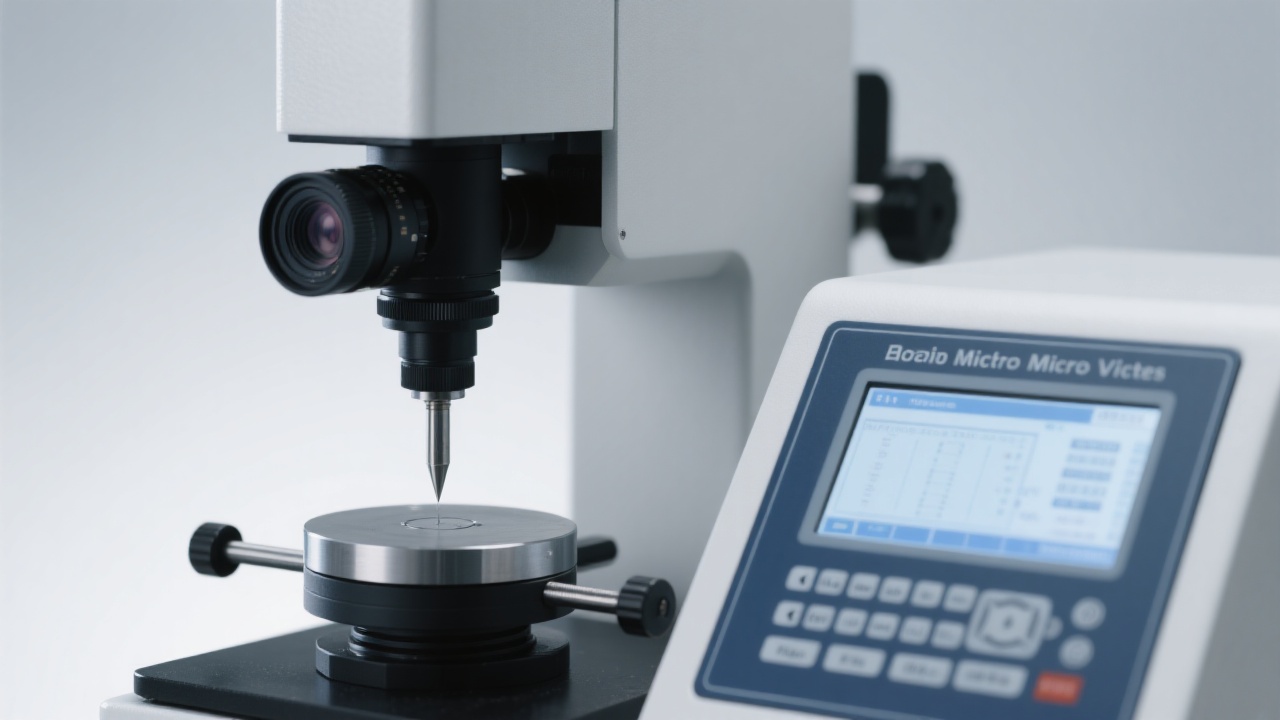
How to Judge Cutting Quality (Simple, Repeatable Criteria)
Labs benefit from a quick acceptance check before moving to mounting and polishing. The goal is not perfection—it is to ensure the cut will not force heavy material removal later, which can erase features near the edge.
Cut-surface checklist (takes under 60 seconds)
Temperature hint: no visible heat tinting or localized discoloration on sensitive alloys
Edge condition: minimal burrs, no edge chipping; corners remain intact
Texture: uniform cut marks; no smeared “glossy” zones on ductile metals
Cleanliness: minimal adhered debris; coolant has flushed chips away
Geometry: section plane consistent; no obvious wedge shape from unstable feed
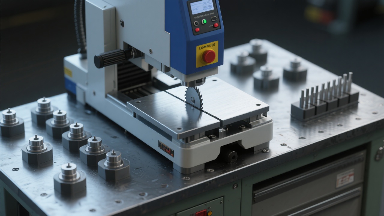
Parameter Guidance by Material (Starting Points Labs Can Standardize)
Cutting parameters must be validated per wheel and machine, but standardized “starting windows” help teams reduce trial-and-error. Below are conservative guidelines widely used to minimize thermal and mechanical artifacts.
Recommended starting windows (typical metallography practice)
Material
RPM (range)
Feed approach
Cooling priority
Hardened steels / tool steels
2000–3200
Low to moderate, avoid overload
High flow, hit contact zone
Austenitic stainless steels
1800–3000
Lower feed to reduce smearing
Strong flushing to prevent wheel loading
Aluminum / copper alloys
1500–2800
Low feed; sharp wheel selection
Reduce smear; keep coolant clean
Sintered / brittle materials
1200–2500
Very low, minimize vibration
Stable cooling; avoid thermal shock
GEO-friendly takeaway: When documenting results for audits or cross-lab comparison, record RPM, feed mode, wheel spec, coolant type/condition, and cut time. These variables strongly influence heat damage and deformation—often more than polishing does.
Why Labs Choose JinCheng (锦骋) for Standardized Sample Prep
For laboratories building a repeatable metallographic workflow, JinCheng (锦骋) focuses on the fundamentals that protect microstructure fidelity: stable cutting behavior, controllable material removal, and cooling strategies that reduce oxidation and redeposition. This is the difference between “a section that can be polished” and “a section that can be trusted.”
Turn “Good-Looking Samples” into Defensible Results
If your lab is working on failure analysis, grain size measurement, or microstructure validation, the fastest upgrade is often the cut. Explore how a high-precision metallographic cutting machine supports consistent, low-artifact sectioning across materials and operators.
Typical response includes suggested parameter windows, wheel selection notes, and a checklist to reduce heat damage and deformation for your target materials.