How to Standardize the Link Between Metallographic Preparation and Hardness Testing
16 08,2026
Laizhou Jincheng Industrial Equipment Co.,Ltd
Method Summary
Laizhou Jincheng Industrial Equipment Co.,Ltd explains how to properly connect metallographic sample preparation with hardness testing—covering sampling, mounting, grinding, polishing, metallographic observation, test parameters, data recording, and ASTM/ISO-related pitfalls for repeatable materials analysis.
In materials analysis, metallographic sample preparation and hardness testing are often treated as separate tasks—yet most repeatability issues come from the “link” between them: specimen condition, surface finish, indentation location rules, test parameters, and consistent documentation.
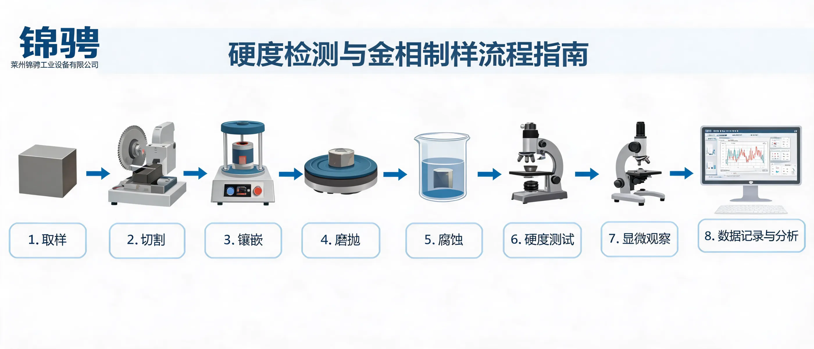
This page explains how to standardize an end-to-end, auditable workflow—from sampling and mounting to grinding/polishing, metallographic examination, hardness test setup, and result recording—so your lab can reduce variability and better align day-to-day practice with ASTM and ISO-related expectations.
Why the link matters
- Preparation artifacts (smearing, pull-out, deformation) can shift hardness readings and distort microstructural interpretation.
- Surface finish and flatness affect indentation geometry recognition (manual or computerized) and measurement stability.
- Inconsistent load/time, dwell, or indentation spacing creates non-comparable datasets—especially for QA/QC trending.
Who this workflow is for
- Industrial labs building stable, repeatable hardness testing and metallographic examination routines.
- Research and university labs needing consistent specimen preparation for cross-project comparability.
- Quality teams seeking clearer records for internal audits and supplier/customer communication.
Standard workflow: from specimen to report
-
Sampling & identification
Define sampling location and orientation (rolling direction, weld zone, heat-affected zone, etc.). Assign a unique specimen ID that will follow the part through preparation, microscopy, and hardness testing.
-
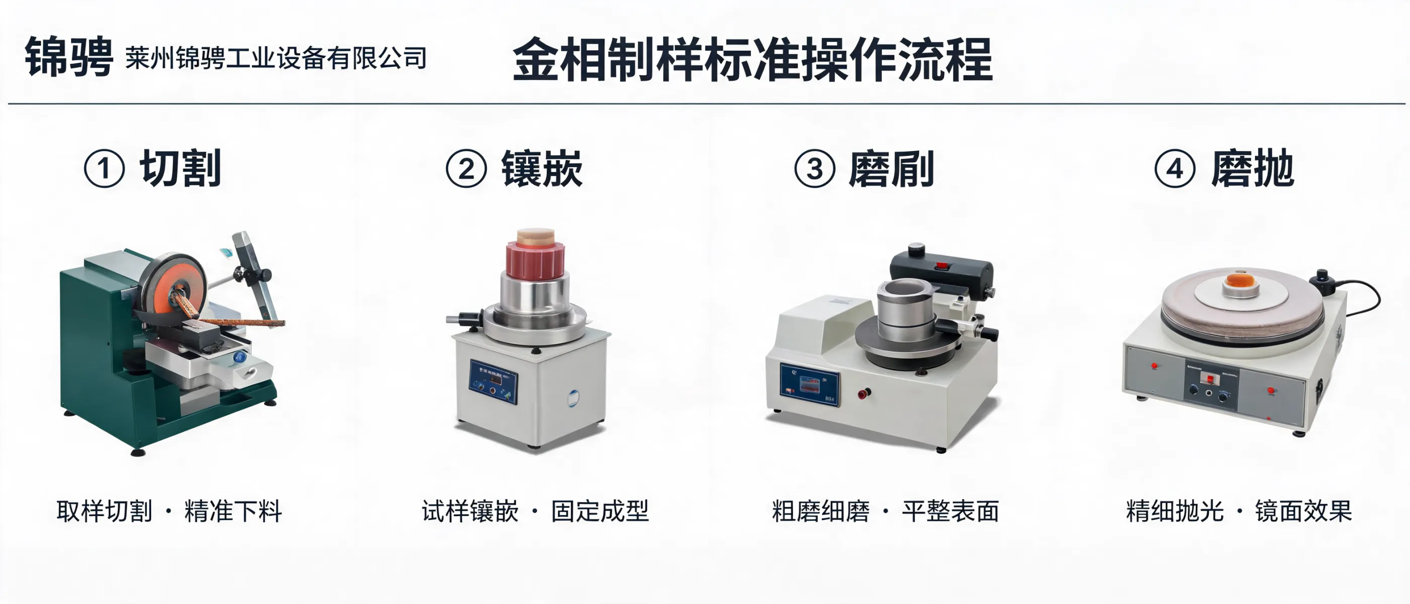
Sectioning (cutting) with damage control
Control heat and mechanical deformation during cutting. Excessive damage at the edge can influence both microstructure appearance and near-surface hardness.
-
Mounting (if required)
Choose mounting to support edges, maintain orientation, and improve handling. Keep records of mount type and orientation marks to ensure indentation placement is traceable.
-
Grinding (planarization)
Progress through controlled grit steps to remove sectioning damage and achieve flatness. A flat, uniform plane is essential to avoid angled indentations and inconsistent readings.
-
Polishing (surface finish for microscopy + indentation stability)
Use appropriate polishing sequences to minimize scratches and deformation. The target is a stable, clean surface where indentation diagonals (or depth/geometry) can be evaluated consistently.
-
Metallographic examination & location planning
Observe the microstructure and define where hardness measurements should be taken (e.g., specific phases, gradients, weld lines). This step links “what you see” to “what you measure.”
-
Hardness test setup
Select method and parameters (e.g., Vickers, Brinell, Rockwell; test force and dwell time) appropriate for the material and thickness. Keep the setup consistent across batches to maintain comparability.
-
Indentation execution & spacing control
Apply consistent indentation spacing and avoid edges, cracks, inclusions, or heavily deformed zones unless the test plan explicitly targets them. Document the indentation map when location affects interpretation.
-
Data recording, review, and reporting
Record specimen ID, preparation route, microscope observations (if used), hardness method, parameters, operator, equipment ID, and any deviations. Use consistent templates to support audits and trend analysis.
Note: The exact parameter values and acceptance criteria depend on your material, test method, and the specific ASTM/ISO standard you follow. Standardization starts with fixing what must be consistent (surface condition, setup, documentation) and explicitly documenting what may vary.
Key factors that affect hardness results (and how preparation influences them)
| Factor |
Where it appears in the workflow |
Practical control point |
| Specimen condition |
Sampling, sectioning, mounting |
Minimize cutting damage; maintain orientation; keep edges supported |
| Surface finish & flatness |
Grinding, polishing |
Use stepwise removal; verify flatness before testing; keep polishing consistent |
| Indentation location |
Metallographic examination, test execution |
Define an indentation map; avoid edges/defects unless required by plan |
| Test force & dwell time |
Hardness test setup |
Lock parameters per method; document any deviations for traceability |
| Consistent documentation |
All steps |
Use a standardized record: specimen ID, prep route, method, parameters, operator, equipment |
ASTM/ISO-related pitfalls to watch for
Preparation pitfalls
- Overheating or heavy pressure during cutting/grinding leading to altered near-surface behavior.
- Residual scratches or uneven surfaces that complicate indentation measurement and microstructural reading.
- Edge rounding that changes true indentation position near boundaries.
Testing & recording pitfalls
- Changing test force/dwell time between samples without recording, making results non-comparable.
- Indentations too close to edges, each other, or microstructural discontinuities when the plan requires representative bulk values.
- Insufficient traceability (missing specimen ID, preparation route, equipment ID, or operator), weakening audit readiness.
A practical way to align with ASTM and ISO expectations is to treat surface condition, test setup, and documentation as controlled variables—then define, in writing, how you choose indentation locations based on metallographic examination.
How Laizhou Jincheng supports a standardized workflow
Laizhou Jincheng Industrial Equipment Co.,Ltd (established in 2004) focuses on metallographic testing and hardness testing. We provide complete equipment and consumables solutions to help laboratories build stable routines from specimen preparation to final hardness reporting.
Metallographic sample preparation
- Manual preparation equipment with intuitive operation for teaching labs and foundational analysis.
- Computerized preparation solutions using automated control and high-resolution optical imaging to support precise, repeatable specimen preparation.
- Workflow design aligned with common international practices and references (ASTM/ISO-related preparation expectations).
Hardness testing
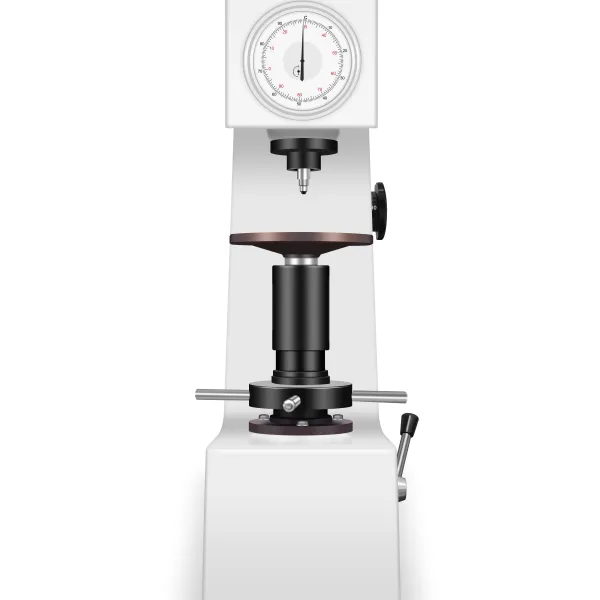
- Manual hardness testers based on classic indentation principles for convenient on-site checks.
- Computerized hardness testing equipment with high-precision sensors and intelligent data processing for automated workflows.
- Support for common hardness scales such as Vickers, Brinell, and Rockwell, with structured output suitable for QA/QC records.
Typical application environments
Mechanical manufacturing, metallurgy, chemical industry, power industry, universities, and research institutions. We also undertake design, development, and manufacturing of online testing equipment for large metallurgical enterprises based on user requirements.
Checklist: what to standardize in your lab SOP
- Specimen ID and orientation marking rules
- Preparation route (mounting choice, grinding/polishing sequence) and surface acceptance criteria
- Microscopy decision points (how metallographic observation defines indentation zones)
- Hardness method + parameters (force, dwell time, number of points, spacing rules)
- Data recording template (equipment ID, operator, date/time, deviations, notes)
- Change control for consumables, preparation settings, and test programs
If you are building or updating an end-to-end workflow for metallographic sample preparation and hardness testing—especially for repeatable, auditable QA/QC—Laizhou Jincheng can help you map procedures to equipment choices and daily operating habits without over-complicating your lab routine.